|
|||||||
| Members' SSPs A place to post up pics of your SSP, whether restored, in-progress, or somewhere in-between. |
 |
|
|
Thread Tools | Display Modes |
|
|
|
#1
 03-26-2017, 06:40 PM
|
||||
|
||||
|
Thanks, Michael, that's very helpful. I think I was confusing the shotgun release buttons and the key with later Crown Vics I've driven that had a momentary rocker switch on the lights control boxes to release the shotgun. They also had a key to unlock it.
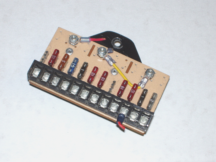
I'm going to check 0327 to see if anything is still left. But with your info, it shouldn't be too difficult to recreate them. I see your CHP fuse block is shown. Is that the original location? I thought I saw something somewhere mentioning they were under the hood, but I don't see any good place to put them.
__________________
******************************************* 1982 CHP 0327 
|
|
#2
03-26-2017, 08:22 PM
|
||||
|
||||
|
Quote:
|
|
#3
03-27-2017, 05:08 PM
|
||||
|
||||
|
Today I spent a few hours revealing 0327's spotlight and antenna ball mounting holes. For the spotlights I used a cylindrical sanding tool with a Dremel and sanded the paint away carefully to show the Bondo spots. Once they were visible I used an Xacto knife to carve away the bondo (first photo). I wanted to be very careful not to enlarge the mounting screw holes.
Removing about a quarter inch of Bondo inside the trunk where the antenna mount is was much more work. I had to be careful because there was Bondo on both sides of the metal. I didn't want to knock any of the outside Bondo off or damage the metal shape and create more body work. Carefully chipping away as much Bondo on the inside as I could with a putty knife then grinding the rest away, I could see where the three bolt holes and the center hole were from the trunk side. I then drilled the bolt holes and the center hole, using the Dremel tool once again to remove the rest of the Bondo to the original-sized center hole. (second and third photos) The ball mount fits perfectly. It was a good day for 0327. A little at a time, just keep moving forward...
__________________
******************************************* 1982 CHP 0327
|
|
#5
03-28-2017, 03:33 PM
|
||||
|
||||
|
Good work! Thank god my car was never "civilianized" and all holes were left intact and unmolested.
|
|
#7
03-28-2017, 03:54 PM
|
||||
|
||||
|
be sure to spray a little etching primer on the holes, inside and out, to prevent any surface rusting etc.
__________________
Jim for the first time since 1998 there is only two left: 1984 Oregon SP unmarked 1986 Idaho SP
|
|
#8
03-31-2017, 10:30 PM
|
||||
|
||||
|
With the great help of Jim (NoDrama43) I now have an NOS Unitrol M131 Wig-Wag Flasher unit for 0327. I had one from 0204 but it was original and had seen better days. And I did not have any instructions on how to connect it. I had even called Federal Signal Corp. (Federal acquired Unitrol's parent, Dunnbar-Nunn, some time ago) technical support for information, but they were unable to help.
Along with the NOS unit came installation instructions with a wiring diagram. I spent a couple of hours today figuring out how this unit wired into 0327's headlight circuit. I found where the wiring harness had been opened up near the master brake cylinder, and where it had been opened right below where the wig wag flasher had been installed on the left side of the engine bay just in front of the shock tower. It was obvious Motor Transport had cut the wires and spliced in the flasher in those two places, reconnecting the cut wires upon decommissioning. It didn't take long to figure out which splice was for which high beam side; the RH was near the firewall. the one for the LH was near the wig wag flasher. One more wire, +12V from the WW terminal on the back of the CC1 completes the circuit. I'll post all photos and more details when I have it installed, wired and working, but for now, and for future restorers, I am posting the installation instruction page in jpeg and pdf formats. The wire I ordered came in so next step is to build some harnesses.
__________________
******************************************* 1982 CHP 0327
|
|
#9
04-01-2017, 07:51 PM
|
||||
|
||||
|
Today I completed installation of the Wig Wag Flasher. Attached to this post are an enlargement of the Unitrol connection diagram and a photo of the flasher installed in 0327.
On the '82 Mustang, the low beam headlights have two filaments. One filament is for low beam only, the other filament is powered up when the high beams are on. As shown in the stock wiring diagram, when the low beams are on, the headlight switch connects power to the low beam filaments but cuts off the power to them and switches power to the high-beam element in the low beams plus to the high-beam filaments when the high beam switch on the steering column is clicked on. Once I located the two places CHP Motor Transport had spliced in to the wiring harness, the next task was to figure out which side went to the headlights and which side came from the headlight switch. Cut the splices, turn on the headlight switch, then check voltage at the wires. The side with +12V is coming from the switch in both cases. I used #4 self-tapping sheet metal screws to attach the flasher to the sidewall, using the original holes. Self-tappers ensured a good ground connection for the case of the Flasher. The +12V input wire (blue in the photo, as in the CHP wiring diagram) would be connected to the WW terminal on the back of the Federal CC1 controller. I don't have the CC1 installed yet so I just touched it to a voltage source to test. The wig wags worked perfectly! Another good day for 0327.
__________________
******************************************* 1982 CHP 0327
|
|
#10
04-01-2017, 08:26 PM
|
||||
|
||||
|
Nice write up, good work! One more task down.
|
|
| Thread Tools | |
| Display Modes | |
|
|


 Hybrid Mode
